
Technical Thursday #044;
We recently completed an exhibit for the Children’s Science Center in Fairfax, VA using an ST Robotics R12 arm.
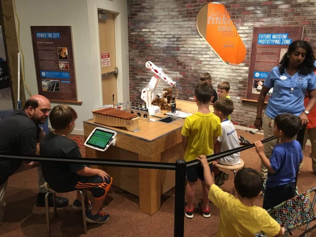
Visitors can program the arm to complete different challenges using a simple drag-and-drop block interface at three tablet stations. If you’re ever in the area, you should go check it out!
In light of our recent experience working with the R12, we want to use this Tech Thursday to write a brief guide to operating the arm. Upon purchasing the R12, you will receive, among other things, a set of PDF manuals and an installer for the Robwin7 program. Read through the first few pages of “R12 manual.pdf” to get all the cables plugged in correctly — at some point you should read the whole thing. Mount the arm to something sturdy by running 4 bolts through the base.
Make sure the USB-serial converter is connected to the front of the control box, and plugged in into your computer. The FTDI drivers should ideally self-install if they are not already installed. If everything is good, you should see “USB Serial Port” under the Ports group in Device Manager:
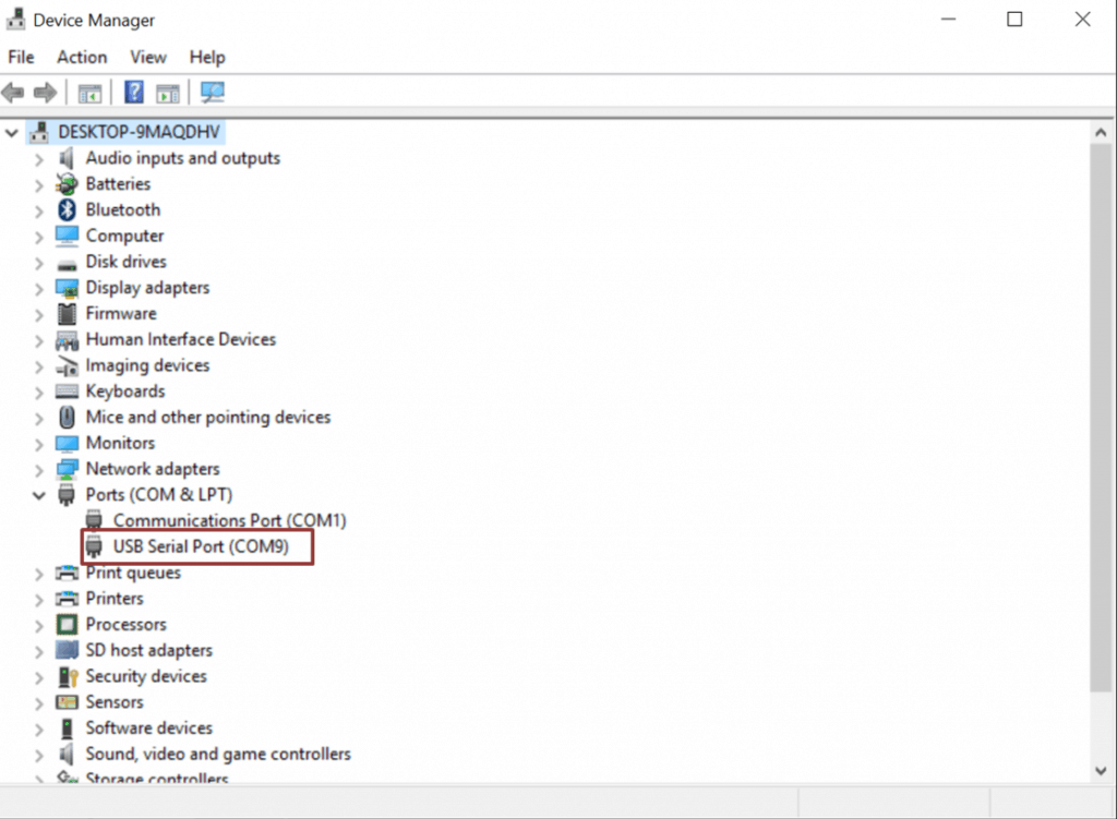
If it’s not showing up, you will need to install the FTDI driver manually. This is pretty much guaranteed to be the case on Windows 10. Don’t worry though, all you have to do is download the driver from the ftdichip website and run CDM21218_Setup.exe. You may need to unplug and replug the USB-Serial converter from your computer. Once you have the drivers sorted out and it’s appearing in Device Manager, check the COM port that it is assigned to; in the example above it’s on COM9. The Robwin7 program only works on COM ports 1 through 9. If yours is outside of this range you need to change it by following these instructions.
Now, with the arm powered off, move the arm by hand into its home position:
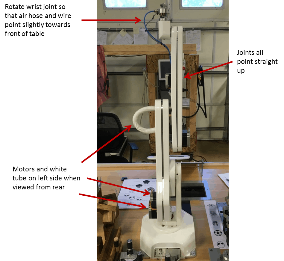
Depending on your grippers you may not have an air hose or wire at the top, so ignore that if needed. You can be off by a few degrees when putting the arm in this position, but try to be as close as possible. The arm needs to start near this position since it assumes this is where it is when it is turned on. Turn the arm on by flipping the power switch on the back of the control box.
Next, install the Robwin7 program by running Robwin7.1.14.msi. Open Robwin7 and go to Comm->Configure. Set Com port to match the COM port you assigned to the USB-Serial converter and set Baud Rate to 19200, then click OK. You should see some text show up in the Communication window. If you get an error message or don’t see any text, consult section 5 of the R12 manual.
From here, you will be operating the arm by typing ROBOFORTH commands to it. All ROBOFORTH commands are in full caps, so hit the Caps Lock key before typing. Whenever you power the arm on, you will typically be sending it these three commands to initialize it:
ROBOFORTH <enter>
START <enter>
CALIBRATE <enter>
If the calibration sequence fails, double check the home position you placed the arm in. You can move the arm by hand while its powered on by sending the DE-ENERGIZE command; this removes power from the motors. To restore power, use ENERGIZE. Then try CALIBRATE again.
After calibrating successfully, the arm will return to its home position. Now, send the READY command to move the arm into a Cartesian-friendly orientation. Put the arm into the desired control mode using either the JOINT or CARTESIAN command.
In JOINT mode, any move commands issued to the arm will be rotation commands about an individual joint. For instance, to move the elbow you can type “TELL ELBOW 100 MOVE” and this will move the elbow 100 stepper motor steps.
In CARTESIAN mode, move commands will auto-compute the joint movements needed to move the arm’s endpoint along the x, y, and z axes. The arm’s endpoint by default is the center of the L-HAND joint (joint 5 // J5). If you set the TOOL-LENGTH variable, the endpoint is offset along the J5 rotation axis. To set the tool length to 100 mm, use “1000 TOOL-LENGTH !”. Note that 1000 means 100.0 mm. The ! is used to set variables. To check a variable’s value, use a ? – “TOOL-LENGTH ?”. To move in Cartesian coordinates, you can use a command in the form “X Y Z MOVE”. The command “1050 0 -552 MOVE” would move the endpoint 105.0 mm in the x direction and -55.2 mm in the z. You can also use MOVETO instead of MOVE, which will give an absolute instead of a relative command.
You can use the WHERE command to see the robot’s current position. When in JOINT mode, this will tell you how many stepper motor steps the joint has rotated about its axis, while in CARTESIAN this tells you the x, y, z position of the endpoint relative to the HOME position in millimeters.
Other useful commands and variables include
- JOG – Used to transfer control to the teach pad. Press Escape to exit JOG mode.
- GRIP and UNGRIP – Used to open and close the electric gripper
- SPEED and ACCEL variables – Set these to control the arm’s speed and acceleration
For more thorough coverage and advanced usage of ROBOFORTH and Robwin, take a look at tutorial7.pdf.