
Introduction
Encoder counts per revolution (CPR) continues to cause questions, so we tested all our motors with encoders to report the data. Admittedly the data sheet from the vendor is very confusing and perhaps erroneous. We have another blog post on encoders that we did on a previous tech Thursday that is more pointed at the theory of encoders.
Encoder Calibration and Basics
The best way to calibrate your robot after putting encoders in them is drive it 10 feet in a straight line, read the number counts, then divide by 120 and you have your counts per inch. It’s going to be the most accurate, you don’t have to worry about gear ratios, etc.
The first thing to know is most of our motors use hall effect encoders. These use a spinning magnet and are not as easy to determine CPR as a optical encoder. So we ran some tests for you folks that have OCD and need to know the exact counts per revolution. Since these are hall effect encoders, they are not super precise. If you want high precision or high CPR you will need optical encoders. The next thing to make sure you understand it the encoder is at the motor! Not the Gear Box! So when we list a gear motor at 122 RPM, that is the gear box! Not the motor! You need the gear box reduction to get the motor RPM. In the case of 122 RPM motors, it has a 1:49 gear box, so the motor will be going 49 times faster.
The hall effect motors will need pull up resistors to work. We have a pull up board that plugs into the encoder to make the wiring a little easier. We also have a dual encoder counter board that has built in pull up resistors.
Another variable in the whole CPR thing is if you are reading a single channel or quadrature reading. Our hall effect encoders are dual channel, the channels are out of phase by 1/2 a step so the direction can be determined. You can also read the rise and fall of each pulse and get your quadrature reading.
Calibration/Testing CPR
So we determined our CPR three different ways.
- Rotating the motor by hand
- Spinning the motor at speed for 60 seconds
- A scope
Rotating the motor by hand…
This isn’t rocket science here. We pulled the back cap off a motor, marked it with a sharpie, and spun it by hand. We had the motor hooked up to a dual encoder counter board and an Arduino Uno, which was spitting out the encoder counts on a debug screen. The Arduino code for the buffer board at the bottom of this post.
So with a IG42 122 RPM motor (just to repeat, the RPM of the gear motor does not matter for this test, we are at the motor end, not the gearbox end) we spun it 10 times and counted 200 pulses, so a single encoder pulsed 20CPR. The Error of this experiment is caused by not stopping and starting the encoder wheel exactly and not being able to spin it uniformly (although technically the buffer board should add/subtract any isolation, etc.) This test was very repeatable. The buffer board is reading in quadrature mode. So the CPR of a single channel of the encoder would be 5 CPR.
Measuring CPR with oscilloscope
This method involved using a tachometer and a power supply. The power supply was adjusted until the gear motor was spinning at 122 RPM (again, this is the gear motor RPM, not the encoder RPM). We take the 122 and multiply the gear ration (1:49) onto the RPM. So 122*49=5978 RPM or 99.6 Rotations per second. We hooked an oscilloscope to the output of channel A and B of the encoders (with pull up resistors) and got the following output.
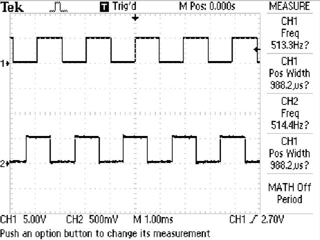
Oscilloscope Screen Capture of encoder output
The frequency was 513Hz (pulses per second). 513 Cycles per second / 99.6 Rotations per second = 5.14 Cycles per revolution (5.14 CPR). The error in this measurement is the tachometer we used to get 122 RPM and the possibility our oscilloscope is inaccurate. 5.14 is pretty close to 5.
Measure the CPR with a Stopwatch and Encoder Buffer Board
The final method we tried was using a stopwatch and counting. We used the same setup and code for the manual spinning of the encoder disk. The motor was hooked up to a dual encoder counter board and a Arduno Uno. We reset the counts, ran for 1 minute at 122 RPM, and recorded the counts. The 122 RPM was calibrated as documented in the Oscilloscope test. After 1 minute we received 123,522 counts. So 123522 counts per minute / 5978 rotations per minute (again, the motor NOT the gearbox output) = 20.66 Counts per rotation in quadrature. So 5.17 CPR. The error here is again caused by possibly not being at 122 RPM based on the tachometer error and stopping and starting the encoder count exactly at 60 seconds (1 minute). Still 5.17 if pretty close to 5 CPR for a single channel.
Conclusion of testing with the IG42 122 RPM Gear Motor
Repeating once again! The encoder is at the motor, not the gear box. So this test can be done on any gear motor, just need to know the gear reduction. The manual spinning the disc seamed to be the most reliable and repeatable method (not to mention the simplest). We received a value of 5 CPR per channel. The Oscilloscope provided a answer of 5.14 CPR. The Timed method provided a answer of 5.17 CPR. Both those methods used the same tachometer, which is probably causing the constant error. The CPR is not going to be a fraction, it’s not possible. So 5 CPR is the final answer.
Other Encoder Testing
We tested all motors with encoders. These values are for reference only. Final calibration should be performed by yourself on your machine with your setup. As mentioned earlier, the easiest way to calibrate your robot, its to install the motors in your robot, then drive it 10ft in a straight line, read the number counts, then divide by 120 and you have your counts per inch. It’s going to be the most accurate, you don’t have to worry about gear ratios, etc.
We tested one of each type of motor using the all three methods above. The results are listed in the tables below. Then we tested every motor and ran them at the same voltage and made sure they all ran at the same approximate frequency of their same type (ie all IG52 encoders ran at about 1100 Hz when the motor was run at voltage). So the CPR determined for each type of motor is listed below.
Test Results:
Did you skip to the end to get the end results? If so just note these values are for reference only! Your results may vary. If you want something more precise and definitive go get motors with optical encoders and pay 2 to 10 times the price…
IG32: 7 CPR, 28 CPR in quadrature
IG42: 5 CPR, 20 CPR in quadrature
IG52: 19 CPR, 76 CPR in quadrature
Remember these values are at the motor, multiply the gear reduction to get the CPR at the output shaft.
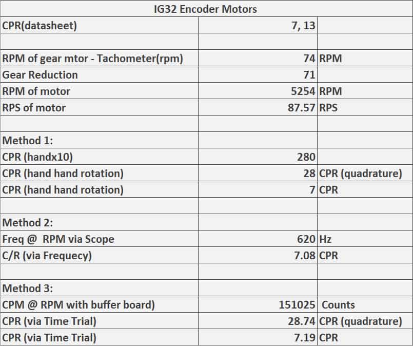
IG32 Encoder Data
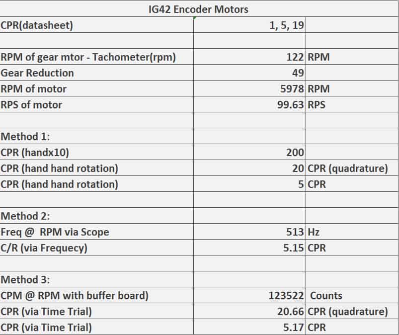
IG42 Encoder Data
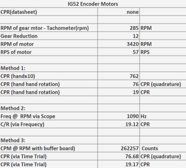
IG52 Encoder Data
Code for using Buffer Board with Arduino
//=========================HEADER=============================================================
/*
   Dual LS7366 Quadrature Counter Test Code
   AUTHOR: SuperDroid Robots
   DATE: January, 2016

   This is a test program to read encoder counts
   collected by the LS7366 breakout board. The counts are
   then displayed in the Arduino's serial monitor at a
   baud rate of 9600

   Hardware: Arduino Uno R3
   Powered

   LS7366 Breakout    -------------   Arduino
   -----------------                    -------
            MOSI   -------------------   SDO (D11)
            MISO   -------------------   SDI (D12)
            SCK    -------------------   SCK (D13)
            SS1    -------------------   SS1 (D7)
            SS2    -------------------   SS2 (D8)
            GND    -------------------   GND
            VDD    -------------------   VCC (5.0V)

   License: CCAv3.0 Attribution-ShareAlike (http://creativecommons.org/licenses/by-sa/3.0/)
   You're free to use this code for any venture. Attribution is greatly appreciated.

//============================================================================================
*/

// Inclde the standard Arduino SPI Library, please ensure the SPI pins are
// connected properly for your Arduino version
#include

// Slave Select pins for encoders 1 and 2
// Feel free to reallocate these pins to best suit your circuit
const int slaveSelectEnc1 = 8;
const int slaveSelectEnc2 = 9;

// These hold the current encoder count.
signed long encoder1count = 0;
signed long encoder2count = 0;

void initEncoders() {

  // Set slave selects as outputs
  pinMode(slaveSelectEnc1, OUTPUT);
  pinMode(slaveSelectEnc2, OUTPUT);

  // Raise select pins
  // Communication begins when you drop the individual select signsl
  digitalWrite(slaveSelectEnc1,HIGH);
  digitalWrite(slaveSelectEnc2,HIGH);

  SPI.begin();

  // Initialize encoder 1
  //    Clock division factor: 0
  //    Negative index input
  //    free-running count mode
  //    x4 quatrature count mode (four counts per quadrature cycle)
  // NOTE: For more information on commands, see datasheet
  digitalWrite(slaveSelectEnc1,LOW);        // Begin SPI conversation
  SPI.transfer(0x88);                       // Write to MDR0
  SPI.transfer(0x03);                       // Configure to 4 byte mode
  digitalWrite(slaveSelectEnc1,HIGH);       // Terminate SPI conversation

  // Initialize encoder 2
  //    Clock division factor: 0
  //    Negative index input
  //    free-running count mode
  //    x4 quatrature count mode (four counts per quadrature cycle)
  // NOTE: For more information on commands, see datasheet
  digitalWrite(slaveSelectEnc2,LOW);        // Begin SPI conversation
  SPI.transfer(0x88);                       // Write to MDR0
  SPI.transfer(0x03);                       // Configure to 4 byte mode
  digitalWrite(slaveSelectEnc2,HIGH);       // Terminate SPI conversation
}

long readEncoder(int encoder) {

  // Initialize temporary variables for SPI read
  unsigned int count_1, count_2, count_3, count_4;
  long count_value;

  // Read encoder 1
  if (encoder == 1) {
    digitalWrite(slaveSelectEnc1,LOW);      // Begin SPI conversation
    SPI.transfer(0x60);                     // Request count
    count_1 = SPI.transfer(0x00);           // Read highest order byte
    count_2 = SPI.transfer(0x00);
    count_3 = SPI.transfer(0x00);
    count_4 = SPI.transfer(0x00);           // Read lowest order byte
    digitalWrite(slaveSelectEnc1,HIGH);     // Terminate SPI conversation
  }

  // Read encoder 2
  else if (encoder == 2) {
    digitalWrite(slaveSelectEnc2,LOW);      // Begin SPI conversation
    SPI.transfer(0x60);                      // Request count
    count_1 = SPI.transfer(0x00);           // Read highest order byte
    count_2 = SPI.transfer(0x00);
    count_3 = SPI.transfer(0x00);
    count_4 = SPI.transfer(0x00);           // Read lowest order byte
    digitalWrite(slaveSelectEnc2,HIGH);     // Terminate SPI conversation
  }

  // Calculate encoder count
  count_value = (count_1 << 8) + count_2;
  count_value = (count_value << 8) + count_3;
  count_value = (count_value << 8) + count_4;

  return count_value;
}

void clearEncoderCount() {

  // Set encoder1's data register to 0
  digitalWrite(slaveSelectEnc1,LOW);      // Begin SPI conversation
  // Write to DTR
  SPI.transfer(0x98);
  // Load data
  SPI.transfer(0x00);  // Highest order byte
  SPI.transfer(0x00);
  SPI.transfer(0x00);
  SPI.transfer(0x00);  // lowest order byte
  digitalWrite(slaveSelectEnc1,HIGH);     // Terminate SPI conversation

  delayMicroseconds(100);  // provides some breathing room between SPI conversations

  // Set encoder1's current data register to center
  digitalWrite(slaveSelectEnc1,LOW);      // Begin SPI conversation
  SPI.transfer(0xE0);
  digitalWrite(slaveSelectEnc1,HIGH);     // Terminate SPI conversation

  // Set encoder2's data register to 0
  digitalWrite(slaveSelectEnc2,LOW);      // Begin SPI conversation
  // Write to DTR
  SPI.transfer(0x98);
  // Load data
  SPI.transfer(0x00);  // Highest order byte
  SPI.transfer(0x00);
  SPI.transfer(0x00);
  SPI.transfer(0x00);  // lowest order byte
  digitalWrite(slaveSelectEnc2,HIGH);     // Terminate SPI conversation

  delayMicroseconds(100);  // provides some breathing room between SPI conversations

  // Set encoder2's current data register to center
  digitalWrite(slaveSelectEnc2,LOW);      // Begin SPI conversation
  SPI.transfer(0xE0);
  digitalWrite(slaveSelectEnc2,HIGH);     // Terminate SPI conversation
}


void setup() {
 Serial.begin(9600);      // Serial com for data output

 initEncoders();       Serial.println("Encoders Initialized...");
 clearEncoderCount();  Serial.println("Encoders Cleared...");
}

void loop() {
 delay(500);

 // Retrieve current encoder counters
 encoder1count = readEncoder(1);
 encoder2count = readEncoder(2);

 Serial.print("Enc1: "); Serial.print(encoder1count); Serial.print(" Enc2: "); Serial.println(encoder2count);
}